|
|
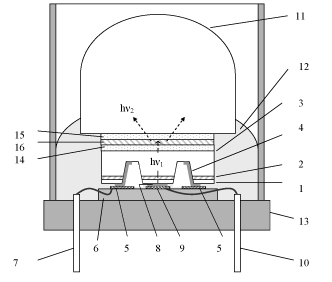
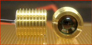
Fig.1 Schematic of III-V mid-IR LEDs ("Big lens option"). 1 – p-type contact layer, 2 – n-type narrow gap layer, 3 – outcoupling substrate surface, 4 – cathode contact, 5 – cathode pad onto Si submount, 6 – Si submount, 7 – negative electrode, 8 – anode contact to mesa area, 9 – anode pad onto Si submount, 10 – positive electrode, 11 – Si hyperhemispherical lens, 12 – epoxy encapsulation, 13 – header. Optically pumped LED: 3 – GaAs LED, 13 – TO-39 package, 14, 15 – optical glue, 16 – InSb “phosphor”, hν1 > hν2 ( see US patent # 6 876 006 with grant date 5 April 2005) Electrically pumped LED : 1 – p-InAsSbP, 2 – n-InAs(Sb), 3 – n+-InAs, 13 – screw header package, 14, 15, 16 – optical glue, hν1 = hν2. "Small lens option" is described here. Sources : 1. T. Kuusela, J. Peura, B. A. Matveev , M. A. Remennyy , N. M. Stus’ , «Photoacoustic gas detection using a cantilever microphone and III–V mid-IR LEDs», Vibrational Spectroscopy, 51(2), 289-293 (2009). 2. Boris Matveev, Maxim Remennyy, Karandashev Sergey, Kimmo Keränen, Heini Saloniemi, Jyrki Ollila, Tom Kuusela, Ismo Kauppinen, «Microimmersion lens LEDs for portable photoacoustic methane sensors», IMCS 2012 - The 14th International Meeting on Chemical Sensors May 20 - 23, 2012, Nürnberg/Nuremberg, Germany, p.241-243, DOI 10.5162/IMCS2012/2.5.5.
|
|
|